|
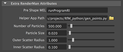
The .rman script should now look like this,
# runProgram.rman file
rman "-version 1" {
Declare param {string rp_python_path} {
label "Helper App Path"
description "The path to the procedural helper app."
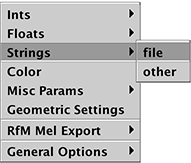
subtype file
range {*.py}
}
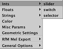
    Declare param {int rp_points_num} {
        label "Number of Particles"
        subtype slider
        range {1 10000 10}
        description "The number of particles to generate."
        }
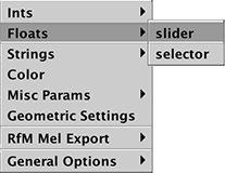
    Declare param {float rp_points_width} {
        label "Particle Size"
        subtype slider
        range {0.001 1}
        description "The diameter of the particles."
        }
}
Although the coding of the .rman script has not been completed it can be pre-visualized
in a browser.
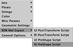
Previewing the UI
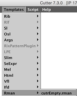
To preview the interface defined by the ".rman" script use the keyboard shortcut
alt + e, control + e or Apple + e. A representation of the user interface defined
by the .rman script will open in a browser - figure 9.
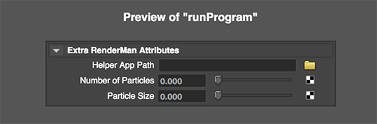
Figure 9
UI previewed in a web browser
Two more float slider widgets must be added to the .rman script. When complete the
script should like this.
|