Setting a Fixed Direction
The first thing to note about the basic_distant shader is that it has two parameters
that enable it's direction to be adjusted. Modern directional lights are written on
the assumption they "face" toward negative Z. For example, the default
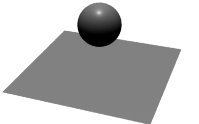
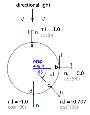
direction of a Maya "directional" light is shown in figure 2.
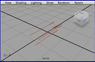
Figure 2
In the case of Maya, the light's transform node (figure 3) enable its orientation to
be adjusted. A modified version of the basic_distant shader is shown below. Note the
"from" and "to" parameters have been removed and it's direction has been "hard wired"
to be negative Z.
Listing 3
|
light
basic_distant(float  intensity = 1;
              color  lightcolor = 1;
            )
{
vector direction = vector "shader"(0, 0, -1);
solar(direction, 0.0) {
    Cl = intensity * lightcolor;
    }
}
|
The rib file, basic_distant.rib, should be edited so that two transformations
provide the rib "equivalent" of the transformations shown in figure 3.
    TransformBegin
        Translate 0 1 0
        Rotate -90 1 0 0
        LightSource "basic_distant" 2 "intensity" 1
    TransformEnd
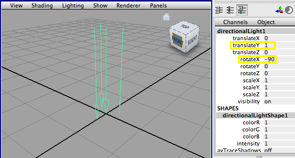
Figure 3
The "shader" Coordinate System
Note that in listings 1 & 2 the direction variable has been assigned xyz values in a
pre-defined coordinate system named "shader" ie.
vector direction = vector "shader" (0,0,-1);
However, had the vector been declared as,
vector direction = vector(0,0,-1);
it would would have been, by default, defined in the camera coordinate system ie. "camera" space.
In other words, the xyz values would be distances meaasured from the origin of the camera.
So, what is "shader" space and why has it been used?
The "shader" coordinate system is identical to the coordinate system that was active when
the light was instanced in the Rib file. Using "shader" space to define
the direction vector, in effect, "parents" the light to the coordinate system that was created
by the TransformBegin statement,
and subsequently transformed by the Rotate and Translate commands that
appear immediately before
the LightSource statement. Consequently, only by defining the direction vector within the
"shader" coordinate system will the light "respond" to the transformations intended to orientate it.
As an experiment, the reader should reset the direction to,
    vector direction = vector(0,0,1);
or
    vector direction = vector "camera" (0,0,1);
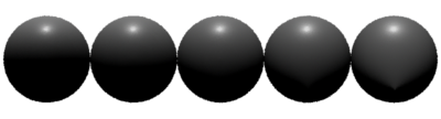
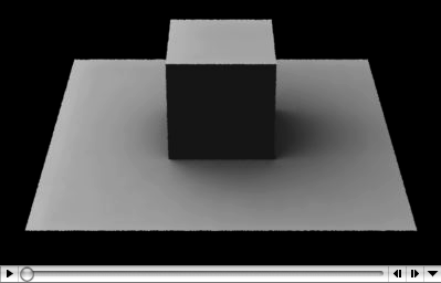
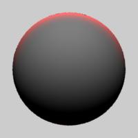
The shader should be re-compiled and the scene re-rendered. Notice that no matter what values
are specified for the Rotate and Translate statements in the Rib file the
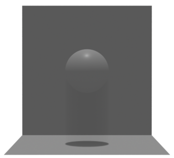
illumination of the scene remains constant. In particular, note the specular hilite on the sphere
(figure 4) indicates the illumination is coming from the camera.
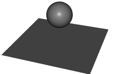
Figure 4
|